


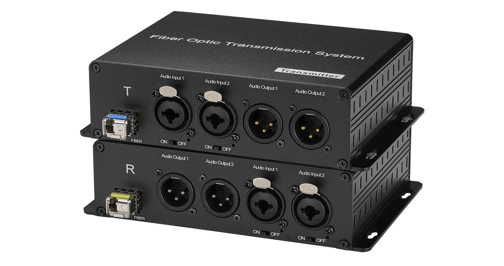
Passive Microphone 48V Phantom Power XLR Audio Over Fiber Optical 2 Channel BIDI Audio Signals
Passive Microphone 48V Phantom Power XLR Audio Over Fiber Optical 2 Channel BIDI Audio Signals
SPECIFICATIONS
Brand Name: NONE,Ho- Link
Certification: CE RoHS FCC
Fiber connector: FC
High-concerned chemical: none
Item Type: cable
Model Number: HL-48V-202XA
Origin: Mainland China
Power Supply: DC12V/ AC110~240V
Power dissipation: lower 2W
Receiver sensitivity: high than -24db
Transmitter power: high than -7db
Warranty Time: 3 years
Wavelength: 1310nm & 1470nm~1610nm (selected according to the function of the device)
Passive Microphone 48V Phantom Power XLR Audio Over Fiber Optical 2 Channel BIDI Audio Signals
Features
1. Through CWDM technology, it can realize the transmission of one to multiple-channel XLR analog balanced audio
2. Each audio channel supports a 48V phantom power switch key. According to the field demand can adjust the phantom power switch, with high flexibility
3. Using FPGA, digital code, and clock recovery technology, high integration and high stability
4. Automatic high-pass filtering to isolate the DC offset
5. High-intelligent noise reduction system for soft rising or falling ramp waves and simulated squelch with a 100dB signal-to-noise ratio (SNR) without popping sound operation
6. Audio interface is in level 3 lightning protection, up to IEC61000-4-5 (8/20μs) differential mode: 6KV
7. Standard single-mode transmission distance of 20 KM
8. LED status indicator to monitor the running status of the device
9. Plug and play, no setup required
10. Devices are used in pairs. Note that devices are distinguished between the transmitter and the receiver
Specifications
Fiber parameter | ||
Wavelength |
1310nm & 1470nm~1610nm (selected according to the function of the device) |
|
Transmitterpower |
>-7db |
|
Receiver sensitivity |
>-24db |
|
Fiber connector |
FC(SC,ST,LCoptional) |
|
Audio parameter | ||
Signal level |
0-8Vp-p |
|
Dynamic bandwidth |
101 dB |
|
Total harmonic distortion (THD) |
-90 dB |
|
Samplingfrequency |
192 KHz |
|
Audio A / D sampling |
24 Bit |
|
Signal-to-noise ratio(SNR) |
100 dB |
|
Amplitude-frequency characteristic |
≤±0.5 dB |
|
Audio input /output impedance |
And 600 Ω in equilibrium |
|
Audio maximum input /output voltage |
0~4V /0~2.5V |
|
Audio gain |
±0.1 dB |
|
Maximum input level |
≥9.5 dBm |
|
Non-linear distortion |
≤0.2% |
|
Audio physical interface |
Dual-on (Transmitter) |
|
Cannon Head (receiver) | ||
Working parameter | ||
Working temperature |
-20 to 70°C |
|
Storage temperature |
-40 to 85°C |
|
Relative humidity |
5 to 95% (non-condensing) |
|
Working life |
> 100000hours |
|
Power supply mode | ||
Desktop type |
DC 12V1A |
|
Power dissipation |
<2W |
|
Rack type |
AC 110~240V 50/60Hz |
|
Pictures



Application
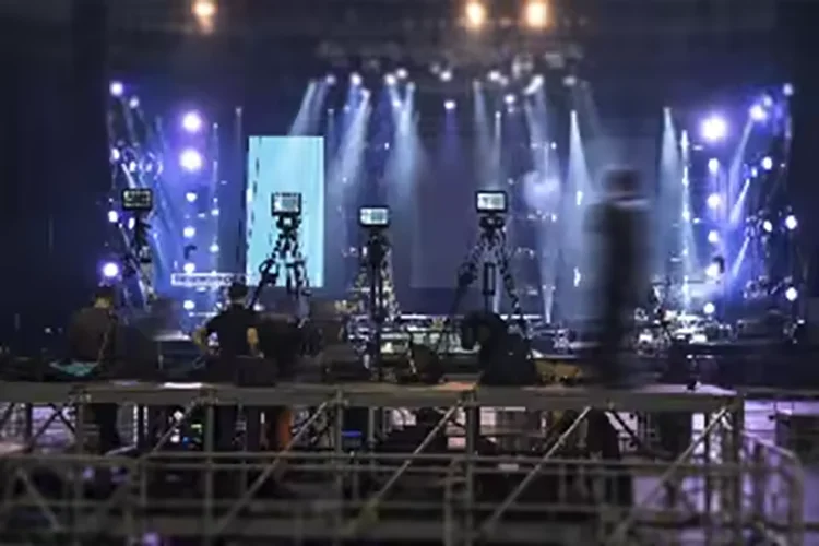
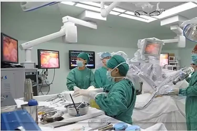
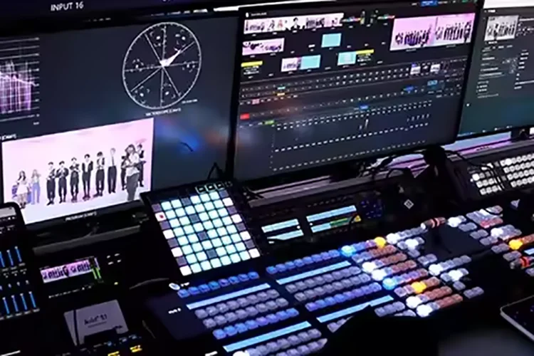
1. SMPTE compatible with serial digital interface
2. UHDTV/4K/8K/HDTV/SDTV video
3. IP media gateway
4. Digital video processing and editing

Connection Diagram

Reminder
1. It is recommended to use the short optical fiber link for the first time to ensure that all the functions of the equipment are normal, and then do long-distance transmission
2. The signal of the fiber optic converter can be output to the power amplifier, but the audio source of the power amplifier can not output the audio source signal to the fiber optic converter, otherwise the equipment will be burned
Troubleshooting of indicator
1: Power indicator is abnormal (POWER)
Answer: Check whether the power adapter meets the equipment requirements or the power adapter fails
Whether the socket is not tight or loose
2: Fiber indicator is abnormal (FIBER)
Answer: Check whether the optical fiber interface is loose and not plugged in
Check whether the optical fiber is too attenuated
3: Video indicator is abnormal (VIDEO)
Answer: Check the signal source
Replace the video cable
4: Data indicator is abnormal (DATA)
Answer: Check the COM port, whether the baud rate is consistent
Check whether the serial port cable is connected backward
Attention
Lightning protection, static electricity and grounding:
It is recommended that when install the device, consideration should be given to the impact of grounding by lightning, and take prevention measures. Strong static electricity will damage the optical device and data chip in the equipment. It is recommended that when plug/unplug the data port of the optical converter, please disconnect the power supply of the optical converter first.
Fiber and optical components:
Be careful when plugging the optical fiber as optical components of the optical converter is very fragile, and it should avoid causingdamage to the optical components. It should be noted that the light source produced by the optical components of the optical converter will be harmful to eyes, so do not have direct eye contactwith the optical components of optical converter. If you need to detect the optical power of the optical converter, please use the optical power meter.
Equipment and installation procedures:
1.Optical fiber installation: please carefully insert the optical fiber into the optical fiber interface of the optical terminal after confirming that the optical fiber link meets the installation requirements.
2.Equipment installation: The equipment can be distinguished between transmitter and receiver, and it is stated clearly on the label and printed on the chassis of the equipment.
Package Reference
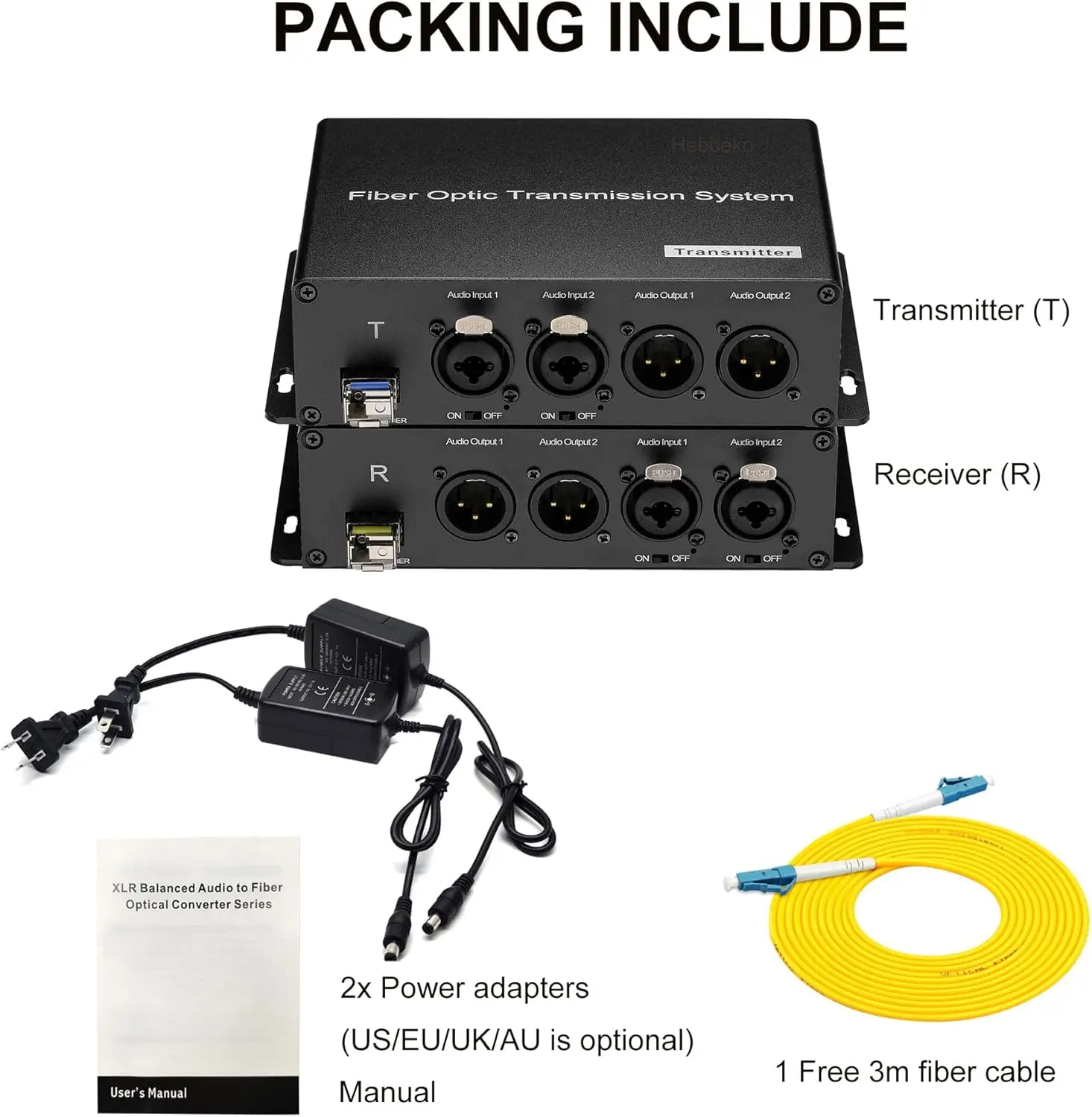

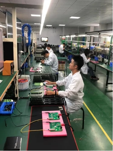
Production & Testing
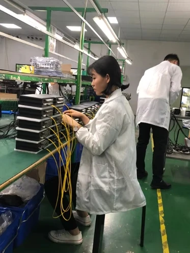
Lari Xiao
Couldn't load pickup availability
92 in stock
View full details


